Four additional tasks that are not directly part of the building process, but which I thought were necessary are included in the section I'm calling Building Aids. They include items that will aid in the building process. So lets get started in this section.
Instrument Panel
The Instrument Panel comes in three sections. A map box is built into the right section.
Currently I've painted the panel a flat black to help reduce glare, but the color may change.
Seat Backs
The two seat backs were constructed and installed. There is a forward and back position on each. The seat backs are attached with hinges. You'll see the hinge halfs on the seat floor in later photos, when the seat backs are removed.
Wire Harnesses
There are two wire harnesses that run down through the plane.
All wires are color coded and cut to length. You've just got to route them to the right places.
Each bundle is neatly tie wrapped and put into place. One of my most difficult tasks, so far, is just getting the wire buddles over the top of the rudder peddle bars.
Flaperon Controls
The Flapperon handle and push-rods were constructed and installed between the seats.
The push-rods are attached to the two joy-sticks on the left and to the flaperons on the right.
The Flaperon control rods run down the center. More on this later.
Tail Fairing
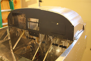
The fiberglass Tail Fairing houses the horizontal stabilator servo and bell crank. This is the top view.
Tail Fairing bottom view.
Fuel and Brake Lines and associated elements
Down the center of the plane run all the control lines and wiring. Starting on the left is a rudder cable which is attached to a foot peddle. Next are the two wire bundles which split off as they run aft. Next is the small aluminum return fuel line. Next are the two plastic brake lines (one for each wheel). Next is the larger fuel line for fuel going to the engine and last on the right is the other rudder peddle cable. At the top of the picture in red is the fuel flow meter.
Moving further aft we see the fuel-shut-off value. It is on the floor just in front of the seats .
This shows the cables and two brown pulleys for the stabilator just behind the front of the seats.
In the center section, behind the passenger seats and between the flaperon push-rods is the fuel pump. The fuel tank will be at the bottom of the picture.
At the very aft end of the center section is the flapperon linkage attached to their push-rods.
Canopy
The canopy is covered with plastic to prevent scratches. Much care is needed when drilling.
The canopy is attached temporarily to the canopy frame. I need to paint the canopy frame before I can rivet the canopy to the frame.
Clamps are shown holding the frame to the roll-bar during the fit-up of the canopy to the canopy frame.
Landing Gear
The wheels were mounted to their rims.
The axles and brakes were attached to the main landing gear struts.
The landing gear struts were attached temporarily to the plane and the wheels were attached to the struts. The nose wheel was also attached. All the gear had to be removed for painting.
Engine Cowling
The fiberglass engine cowling was carefully fitted to the fuselage.
The plane is taking shape. Too bad the engine isn't in there.
This is what it looks like with a light on the inside.
Service Bulletin 12-11-09
These two photos shows the installation of doublers near the landing gear attachment point. The top photo shows that I have removed the necessary rivets before the installation of the doublers. The bottom photo shows the two doublers in place ready to be riveted.
Service Bulletin 12-11-09 was the result of a few builders improper practices. It seems that the bolts used to attach the outboard main gear attach-bracket may have been improperly seated and torqued during initial installation resulting in loose fasteners and possible damage to the landing gear and aircraft structure during landings. Some skin damage was the result on a few planes.
I was fortunate that my plane was still in construction and not even painted. I only had to add the doublers.


No comments:
Post a Comment